OpenGL Moon Simulation
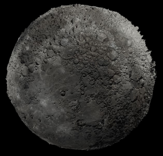
NASA provides a number of color and elevation maps sourced from data assembled by the Lunar Reconnaissance Orbiter camera and laser altimeter instrument teams (located here). I thought creating a realistic rendering of the Moon utilizing the texture and height fields available from NASA would be fun way to dig into OpenGL concepts and GLSL. To start I created a sphere containing ~2M vertices. This allowed for 4 vertices per degree of latitude and longitude. To this sphere I then applied the moon texture.
For purposes of simulating the surface detail I allowed a user to render using two approaches. The first, displacement mapping, reads in the displacement height map floats available. This was then used to recalculate both the vertex locations as well as the surface normals in the fragment and vertex shaders. This approach actually edits the surface geometry and is thus more computationally expensive to setup.
 |
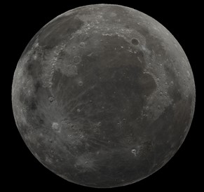 |
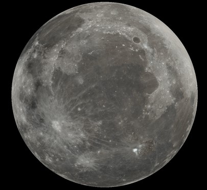
| Texture Only | Displacement Mapping - No Exaggeration |
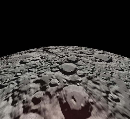
The images above show a rendering of the moon with just the textures applied and no height field mappings on the left, and with displacement mapping applied at the same scale as measured by NASA sensors (not particularly exciting given our distance away in the images).
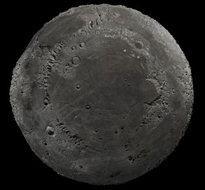
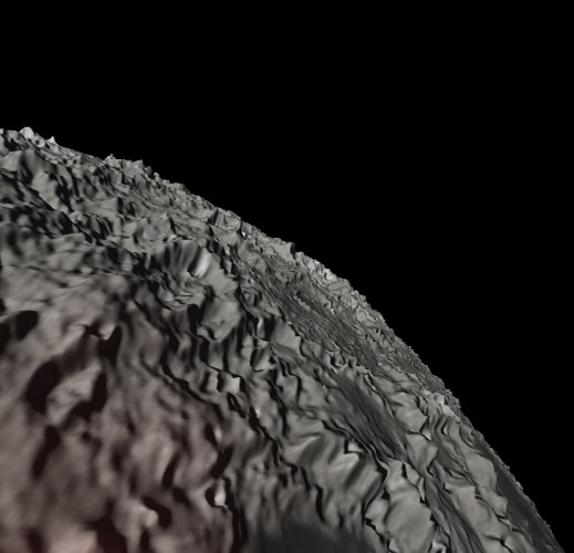
In addition, I also enabled a bump mapping approach. This approach does not edit the the surface geometry. Instead, it simulates the geometry in the fragment shader. My implementation allows a user to shrink/grow the height fields to show an exaggerated view. You’ll notice there isn’t much of a visual difference between the two approaches from far away when looking at the interior of the Moon. If you look at the edges of the moon, however, you’ll easily notice the geometric differences.
 |
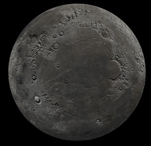 |
| Displacement Mapping - Large Exaggeration | Bump Mapping - Large Exaggeration |
This simulation also features a fly by view available to users. This was created by calculating and placing way points over the sphere, then calculating Catmull-Rom curves between the points to enable a smooth animation path between the way points. This creates a rail that the camera follows while flying and banking across the moon’s surface. This view also highlights the differences between displacement and bump mapping approaches.
 |
 |
| Displacement Mapping - Fly-by - Large Exaggeration | Bump Mapping - Fly-by - Large Exaggeration |
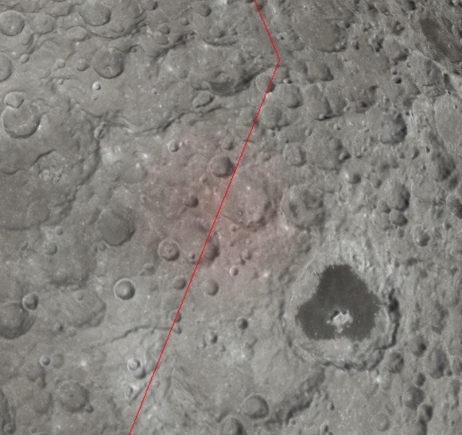
For purposes of rendering the moon I used a combination of BMP textures and TIF displacement maps. I quickly learned that the way this information is read into the software differs greatly between the two formats. For example, BMP files store pixels with bytes detailing the rows starting from the bottom of the image to the top. The TIF files utilized for this process store the displacement detail with bytes starting from the top of the image to the bottom.
Incorrectly pulling in file detail can cause obvious disconnects. The image to the below shows the result of incorrectly mapping height fields to texture detail. This image shows the same geographic location as that in the images above, but with the height maps not corrected for file format differences. You can see it leads to a very different scene.
 |
 |
| Incorrectly Mapped Height Fields | Fly-by Example |
The BMP texture file detail was easy to extract, but the TIFF detail for the height field maps was a bit more complicated. I utilized the TIF specification standards and built a TIF reader class. The class written for this purpose allows a user to read in both the UInt and float displacement maps located at the previously mentioned NASA website. The TIF specification is fairly broad, and thus no attempt was made to handle TIFs that would contain features such as compression or tiling as they were outside of the scope required for reading the NASA provided displacement map.